
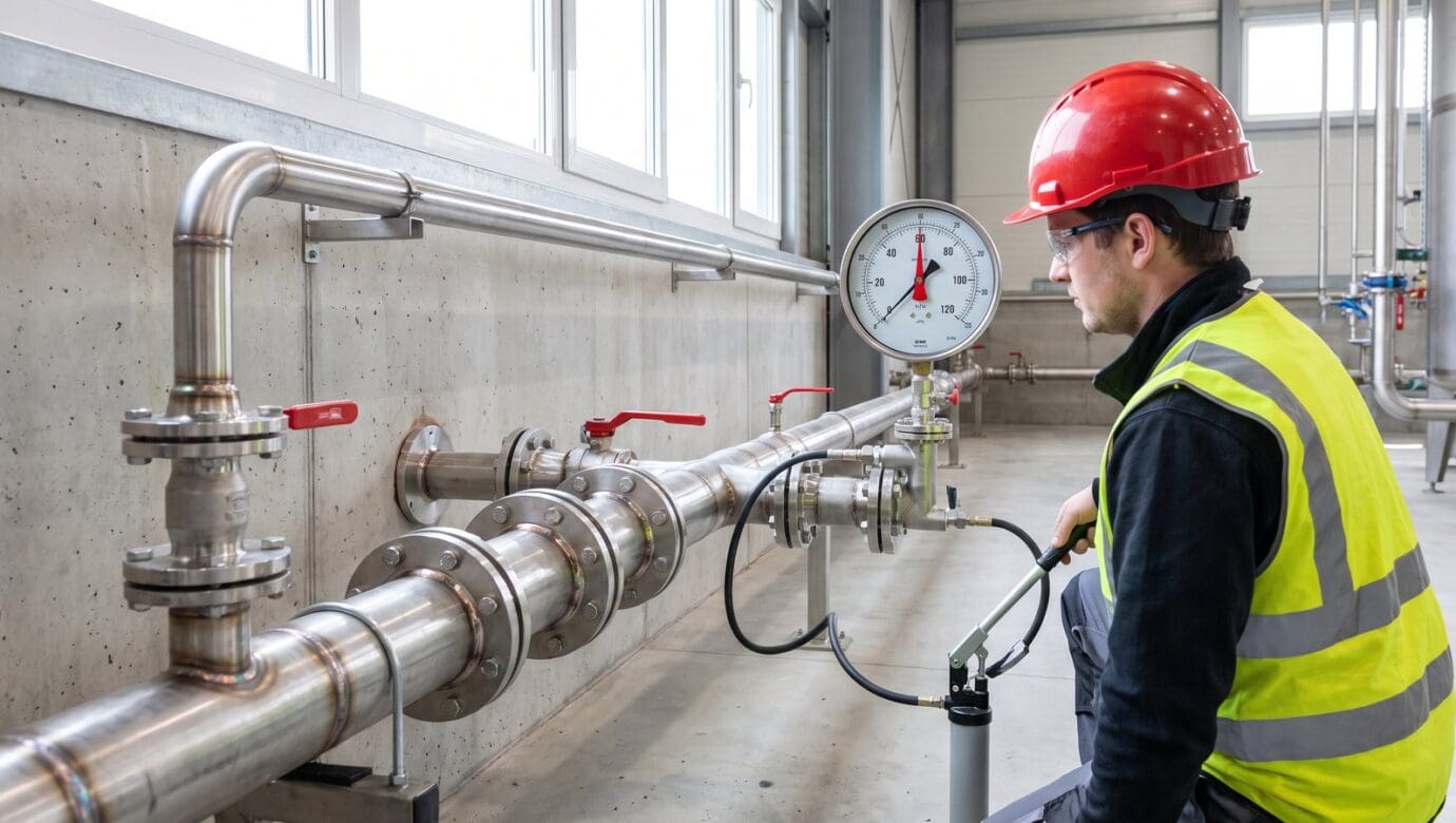
Hydrostatic Test for Piping: Pressure, Procedure and Records
A hydrostatic test fills a finished piping system with water and holds it above design pressure long enough to prove that every weld, joint and component is strong and tight before the line goes into service. For plant process piping built to ASME B31.3, the test pressure is at least 1.5 times design pressure, and building services piping under ASME B31.9 uses the same multiple. Pressure testing and turnover records are part of the industrial process piping work our pipefitters and fabrication shop carry out from Huron.
This guide is for plant engineers, maintenance managers, EHS leads and project managers at manufacturers in Huron, Sandusky, Norwalk, Fremont, Port Clinton, Vermilion and Lorain who are adding a line, tying a new reactor or skid into an existing system, or reviewing a contractor’s test plan. It stays on the test itself. For how chemical and coatings plants specify, weld and document their piping overall, see our guide to chemical and paint plant piping and our industrial market page.
Key takeaways
- A hydrostatic test proves structural integrity and pressure tightness, and it means the most when weld examination and documentation stand behind it.
- B31.3 process piping and B31.9 building services piping are both tested hydrostatically at a minimum of 1.5 times design pressure and held at least 10 minutes, and some owners require a much longer hold.
- No component inside the test boundary should see more than its own maximum test pressure, so lower-rated parts are removed, blanked or isolated first.
- A pneumatic test stores far more energy than a water test and is reserved for systems that cannot take water, never for saving schedule.
- The test record names the date, the person, the system, the pressure, the hold and the result, and it goes into the turnover package.
- In Northern Ohio, cold weather, test water disposal and tie-ins to existing piping each deserve their own lines in the test plan.
What does a hydrostatic test prove, and what does it not?
A hydrostatic test is a strength and leak test run with water. NASA’s Glenn Research Center in Cleveland states the purpose plainly in its pressure systems safety manual: the test is meant to verify structural integrity and pressure tightness, and together with appropriate examination, design, construction and documentation, it gives assurance that hazards to people and property are at a minimum. Water is the default medium because it barely compresses, so a rupture under water pressure releases far less energy than the same failure under gas.
The test does not replace the visual and nondestructive examination of welds, which NIH’s facilities group requires before pressure testing begins. It also says little about cleanliness, slope, supports or whether the right material went in, so a clean hydro chart on a line with an unexamined weld is only a partial answer.
The term also covers other equipment. OSHA’s portable fire extinguisher standard requires extinguishers to be hydrostatically tested at set intervals by trained people. This article is about piping: process lines, plant utilities, and the heating and cooling water that serves a building.
Which code sets the test for your piping?
The test pressure, hold time and acceptance criteria come from the code the piping was designed and built to, so the first question on any test plan is which code governs. ASME describes B31.3 Process Piping as covering piping typically found in petroleum refineries and in chemical, pharmaceutical, paper and pulp, semiconductor and cryogenic plants, including its examination, inspection and testing. B31.9 Building Services Piping prescribes requirements through testing for piping systems for building services, in the building or within the property limits.
Owners can also set the code by contract. NASA’s standard for ground-based pressure vessels and pressurized systems states that process piping shall meet the requirements of ASME B31.3 and that other piping shall meet the most applicable B31 code. NIH, for its part, treats code test requirements as minimums that its project officers can increase where critical systems are installed.
| Piping system | Usual governing document | What it means for the test |
|---|---|---|
| Process lines in chemical, coatings, food and other plants | ASME B31.3 | Hydrostatic test at a minimum of 1.5 times design pressure |
| Building services piping such as compressed air, or heating and chilled water where the project specification invokes B31.9 | ASME B31.9 | Hydrostatic test at 1.5 times design pressure or more, held at least 10 minutes |
| Hydronic piping in Ohio buildings | Ohio Mechanical Code, adopting Chapter 12 of the 2021 International Mechanical Code | Test requirements come from the adopted code chapter and the project specification |
| Medical gas and vacuum piping | NFPA 99 | Installer tests, then verification by a party independent of the installer |
| Critical systems named by the owner | The owner’s engineering standard | Higher pressure, a longer hold or added witnesses |
Medical gas is its own world. Our medical gas piping page explains how the installer’s initial pressure, cross-connection and standing pressure tests are followed by verification from a separate party.
How is hydrostatic test pressure set?
For B31.3 process piping, the starting point is 1.5 times the design pressure. SLAC National Accelerator Laboratory’s pressure test procedure summarizes the code requirements in one table: 1.5 times design pressure as a minimum for both B31.3 and B31.9 hydrostatic tests, with SLAC holding process piping for 30 minutes and building services piping for 10. The 30 minutes is SLAC’s own choice: B31.3, as quoted in a DOE assessment of the code against the European piping standard, requires the leak test pressure to be held for at least 10 minutes before every joint is examined. Design temperature can change the final number, so the piping designer’s calculation should set it, not a rule of thumb.
There is a ceiling as well as a floor. NIH’s Office of Research Facilities, in its Pipe Testing Part II guidance, says the test pressure should not exceed the maximum test pressure of any component and that parts with a lower pressure rating shall be isolated, and, citing ASME B31.9, that test stress must not exceed 90% of the specified minimum yield strength or 1.7 times the SE value. In practice that means pulling or blanking instruments, control valves and tanks before the pump starts.
The test rig needs its own protection. NASA Glenn calls for a relief device set at the test pressure plus 50 psi or 110% of the test pressure, whichever is lower, and a calibrated gauge with a range of about double the test pressure. SLAC wants the gauge calibrated within the previous 12 months and sized so the test pressure falls in the middle third of its range.
What does a hydro test procedure look like, step by step?
Every owner writes this a little differently, but the sequence below follows the hydrostatic procedure in NASA Glenn’s manual and the general requirements in SLAC’s. It is the shape a plant should expect in a contractor’s test plan.
- Approve the test plan, naming the code, test pressure, hold time, boundaries, blind flange locations, component ratings, relief valve setting, gauge calibration and exclusion zone.
- Finish weld examination first, and leave joints uninsulated and exposed so they can be seen during the test.
- Remove, blank or isolate lower-rated components, restrain or isolate expansion joints, and use blinds or caps at the boundaries so the test does not load a closed valve seat.
- Fill from the low point and vent the high points. NASA Glenn requires valves at all high points to bleed air pockets.
- Keep nonessential people out of the test zone, and barricade or patrol it while pressure is applied.
- Raise the pressure to 50% of test pressure, hold and check for leaks, then climb in 10% steps, holding at each step until the gauge settles.
- Hold full test pressure for at least 15 minutes, observing from a safe distance, or longer if the code or owner requires it.
- Reduce to a pressure not less than the maximum allowable working pressure, then closely examine every weld and every flanged and threaded joint.
- Depressurize, drain by the route the plan names, return relief devices to their normal setup, and sign the test record.
Leakage shows up as a continuous drop in pressure, but temperature also moves the gauge. NASA Glenn’s procedure calls for monitoring temperature to correct pressure changes, which matters on an outdoor rack when the sun comes out halfway through a hold.
When is a pneumatic test used instead, and why is it riskier?
A pneumatic test uses air, nitrogen or another nonflammable, nontoxic gas. SLAC’s procedure states that pneumatic tests are potentially more dangerous than hydrostatic tests because of the higher level of potential energy, and it allows them only when a system cannot be filled with water or traces of the test medium cannot be tolerated. NASA Glenn adds the case where water would damage linings or internal insulation, and its manual says time or funding are not sufficient reasons to request an alternate test.
The hazard is not only a leak. NASA Glenn lists shrapnel, explosive noise, a pressure wave and whip action from a gross rupture, and it sizes the restricted area to the distance where blast overpressure falls to 0.5 psi, a level that may shatter glass windows. It treats combination hydrostatic and pneumatic tests as just as hazardous, and it does not pneumatically test brittle materials such as glass and cast iron.
The numbers change too. SLAC’s table lists B31.3 pneumatic tests at 1.1 to 1.33 times design pressure, with a first leak check at a low pressure of no more than 25 psig, and the system reduced to design pressure before anyone examines it. NASA Glenn notes that pneumatic test pressure is typically 110% of the maximum allowable working pressure or design pressure. SLAC requires a relief valve on every pneumatic test, and NIH requires overpressure protection and a safety plan.
What water should you use, and where does it go afterward?
NASA Glenn’s manual says test water shall be clean and of a quality that minimizes corrosion of the materials under test, and that its temperature shall not exceed 120 °F unless a higher test temperature is specified and approved. On stainless steel lines, the practical questions are where the water comes from, how long it will sit, and how quickly the line will be drained and dried. Those choices belong in the test plan before the fill, and our guide to 304 versus 316 stainless steel process piping covers how the two alloys differ.
Weight is the other surprise. NASA Glenn warns that systems designed for gas or vapor may need temporary support or bracing to carry the weight of the test water. A compressed air header hung for a light fluid can load its hangers far more heavily full of water than it ever will in service.
Disposal is a decision, not an afterthought. SLAC’s procedure has the test fluid disposed of as described in the test plan. Ohio EPA keeps a general NPDES permit for hydrostatic test water, OHH000004, and its listing of facilities covered by that permit includes Columbia Gas transmission work in Lorain County and the Intel Ohio site in New Albany. Plant tests are usually far smaller, but if the water may carry oil, residue or treatment chemicals, the owner’s environmental lead should choose the drain, the tank or the permit route before the fill.
What should a hydrostatic test record contain?
A test that was never written down did not happen, as far as an inspector or a future engineer is concerned. For plants covered by OSHA’s process safety management standard, the mechanical integrity requirements of 1910.119 apply to piping systems and components such as valves, require testing to follow recognized and generally accepted good engineering practices, and require each test to be documented with the date, the name of the person who performed it, an identifier for the equipment, a description of the test and the results.
A record worth keeping also names the code, the boundaries, the test medium, the pressure and hold time, the gauge and its calibration date, the relief valve setting, any leaks and repairs, and the witness. SLAC requires a separate record for every test even when one approved plan covers several, and its custodians keep plans and records for five years.
The record then belongs in the turnover package. Our orbital welding page describes a turnover package that normally includes the welding procedures and welder qualification records, mill test reports and heat numbers, purge and weld data, and the pressure test and turnover records for the completed system. Tying the test record to the weld map is what lets a plant trace a future leak back to a joint and a heat number.
What happens when a hydrostatic test fails?
Many failures are small: a weeping flange gasket, a threaded fitting, valve packing or a pinhole in a weld. NASA Glenn’s acceptance standard is that the piping, apart from possible localized leakage at pump or valve packing, shows no visual evidence of weeping or leaking, and if signs of yielding appear, the pressure is slowly decreased to zero.
Repairs should never be made on a pressurized line. OSHA’s lockout/tagout standard requires that all potentially hazardous stored or residual energy be relieved, disconnected, restrained and otherwise rendered safe, and a filled test section holds stored energy until it is bled down. After the repair, the joint is examined again and retested, and SLAC notes that a retest should not exceed the original test pressure. A weld leak also calls for a look at the joints made around it, and the repair and passing retest go into the record.
What changes when you test piping in Northern Ohio?
Weather is the biggest local variable. NASA Glenn does not allow hydrostatic tests with water when the ambient temperature is below 40 °F, and along the lake shore that rules out many outdoor and unheated-space tests for a good part of the year unless the area is enclosed and heated. A line filled in a cold building also has to be drained completely before the crew walks away.
What this means in Ohio: Plan outdoor and unheated-space tests around the 40 °F guideline NASA Glenn uses in Cleveland, settle the water route before the fill, and remember that hydronic piping in Ohio buildings falls under the Ohio Mechanical Code rule for hydronic piping, which incorporates Chapter 12 of the 2021 International Mechanical Code. A process line and the heating loop in the same building can answer to different documents.
Tie-ins to existing piping deserve as much planning as the new work. At AkzoNobel in Huron, our turnkey installation of a new reactor ran stainless steel welded process piping across seven separate buildings, combining new installations with integration into legacy systems while keeping disruption to ongoing production to a minimum. On work like that, the test plan has to show exactly where new piping ends and existing piping begins, because existing lines and valves may not be rated for the new test pressure and must be isolated. Prefabricated piping skids are usually pressure tested in the shop before shipment, which leaves the tie-ins as the field work.
Frequently asked questions
What is the difference between a hydrostatic test and a pneumatic test?
A hydrostatic test pressurizes the piping with water, while a pneumatic test uses air, nitrogen or another nonflammable, nontoxic gas. Because compressed gas stores much more energy, a pneumatic failure can throw fragments and create a pressure wave, so pneumatic tests use lower pressures, larger restricted areas and relief protection, and they are reserved for systems that cannot be filled with water.
How long does a hydrostatic test last?
The hold at full test pressure is usually measured in minutes. B31.3 and B31.9 both set a minimum of 10 minutes, NASA Glenn holds for at least 15 minutes, and SLAC holds B31.3 process piping for 30 minutes, while NIH prefers a 4-hour hydrostatic test on hydronic systems because of its history with leaks. Filling, venting, staging the pressure, examining and draining all add time.
Can a hydrostatic test damage the piping?
It should not, if the pressure is set correctly and the boundary is right. B31.9 limits test stress to 90% of the specified minimum yield strength, lower-rated components are isolated, expansion joints are restrained, and gas lines get temporary supports where the water weight calls for them. The risks come from skipping those steps, from freezing, or from water left standing after the test.
Who should witness a hydrostatic test?
The owner decides, and the test plan should say so. SLAC requires a trained pressure system inspector to witness every test, and plants under OSHA’s process safety management standard must record the name of the person who performed each test. At a minimum, the contractor’s foreman or quality lead and the owner’s representative should watch the hold and sign the record.
Does piping need a new pressure test after a repair or alteration?
Under SLAC’s procedure, yes: a pressure test is required for a new pressure system before use and for an existing system after repair or alteration. The governing code and the owner’s standard set the details, and a retest should not exceed the original test pressure. If a line cannot be taken out of service and filled, the alternative should be agreed in writing first.
Talk to Wilkes about your project
Bring the line list or isometrics, the design pressure and temperature for each system, the governing code and any owner testing standard, the materials, the tie-in points to existing piping, and your outage windows. If the job includes skids or shop-built spools, bring their test records too, so the field test plan can pick up where the shop left off. Wilkes Plumbing & Heating has been in business since 1912, and its pipefitters and fabrication shop work out of Huron. Process piping is project work, and it takes its crews across Ohio.
Wilkes Plumbing & Heating is at 205 Sprowl Rd, Huron, OH 44839, serving Huron, Sandusky, Norwalk, Port Clinton, Vermilion, Lorain, Fremont, and the surrounding counties. Call (419) 433-2325, or request a quote.
Keep reading
Commercial Natural Gas Piping in Ohio: Sizing, Pressure and Code
A practical guide to the gas system a building owner is responsible for, from the meter outlet to each appliance valve: who owns it, how it is sized, which pressure to run, and how it is tested before gas goes in.
Dust Collection System Design for Plants: Ducts, Fumes, NFPA 660
A collector performs only as well as its hoods, its ducts, and the air the building has to give back. A plant-floor guide to capture, transport velocity, explosion protection and Ohio permits for dust and fume systems.
Turnkey Process Piping and a Reactor Install at AkzoNobel
A look inside a turnkey reactor installation and stainless steel process piping scope spread across seven buildings at a Huron, Ohio chemical plant, sequenced so production never stopped.
Need this handled at your facility?
Wilkes engineers, fabricates, and installs process piping, plumbing, and HVAC systems across Ohio.